Project Overview
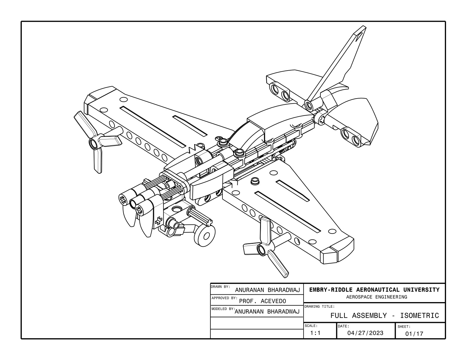
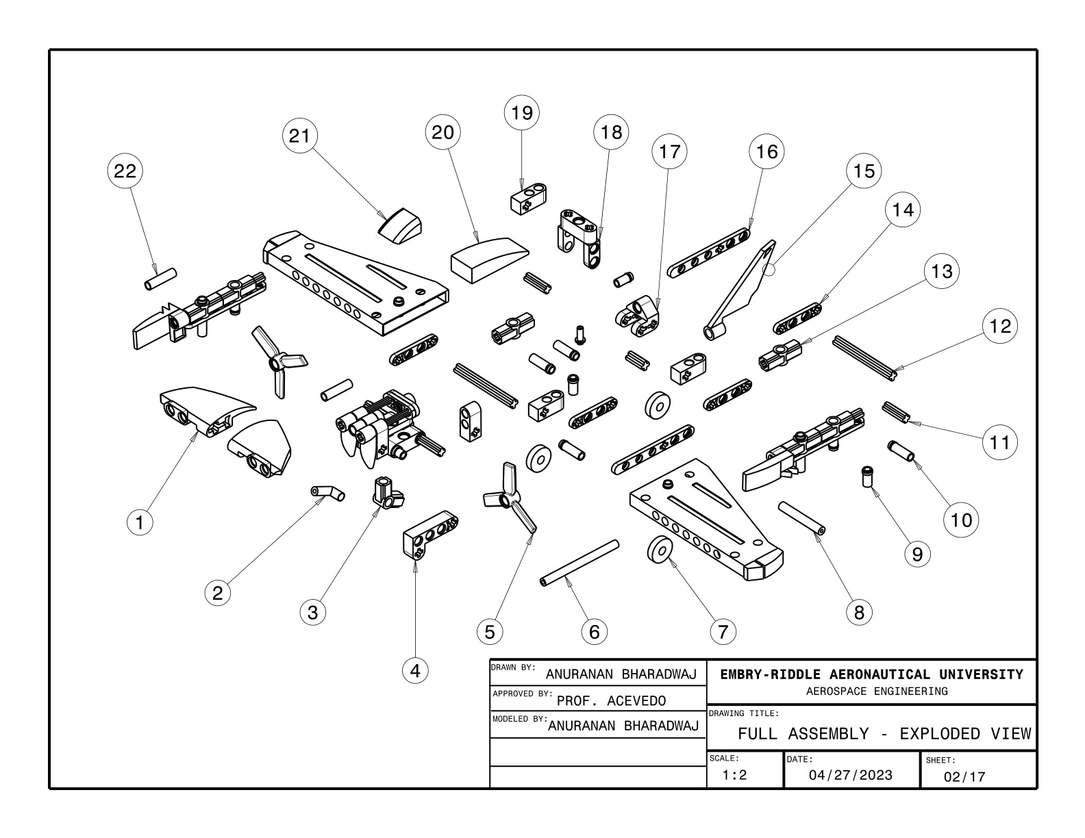
The EGR 120 final project required designing a complete LEGO airplane model and producing a formal engineering drawing package that documents the design to industry-standard drafting conventions. The project covered the full design-to-documentation workflow: digital 3D modeling using LEGO-specific CAD software, photorealistic rendering, and the translation of a 3D assembly into a structured set of 2D engineering drawings in SolidWorks.
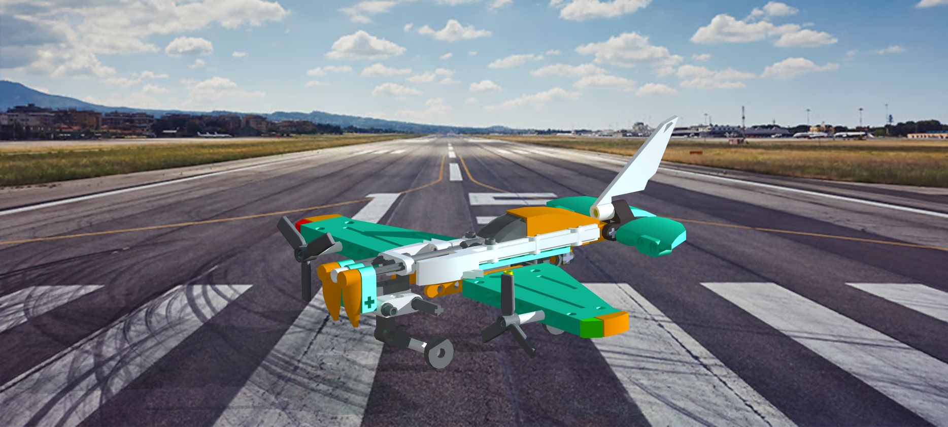
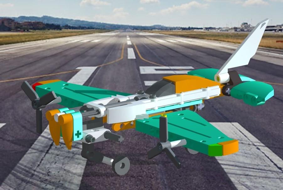
The airplane was designed with an emphasis on visual accuracy and structural plausibility — selecting LEGO parts whose geometry approximates real aircraft components such as fuselage panels, wing surfaces, engine nacelles, and landing gear struts. The finished design is a twin-engine aircraft featuring a T-tail empennage and tricycle undercarriage, rendered against a runway background to simulate a real aircraft environment.
- Design a recognizable airplane configuration using authentic LEGO components in BrickLink Studio
- Produce a photorealistic rendered image of the completed model
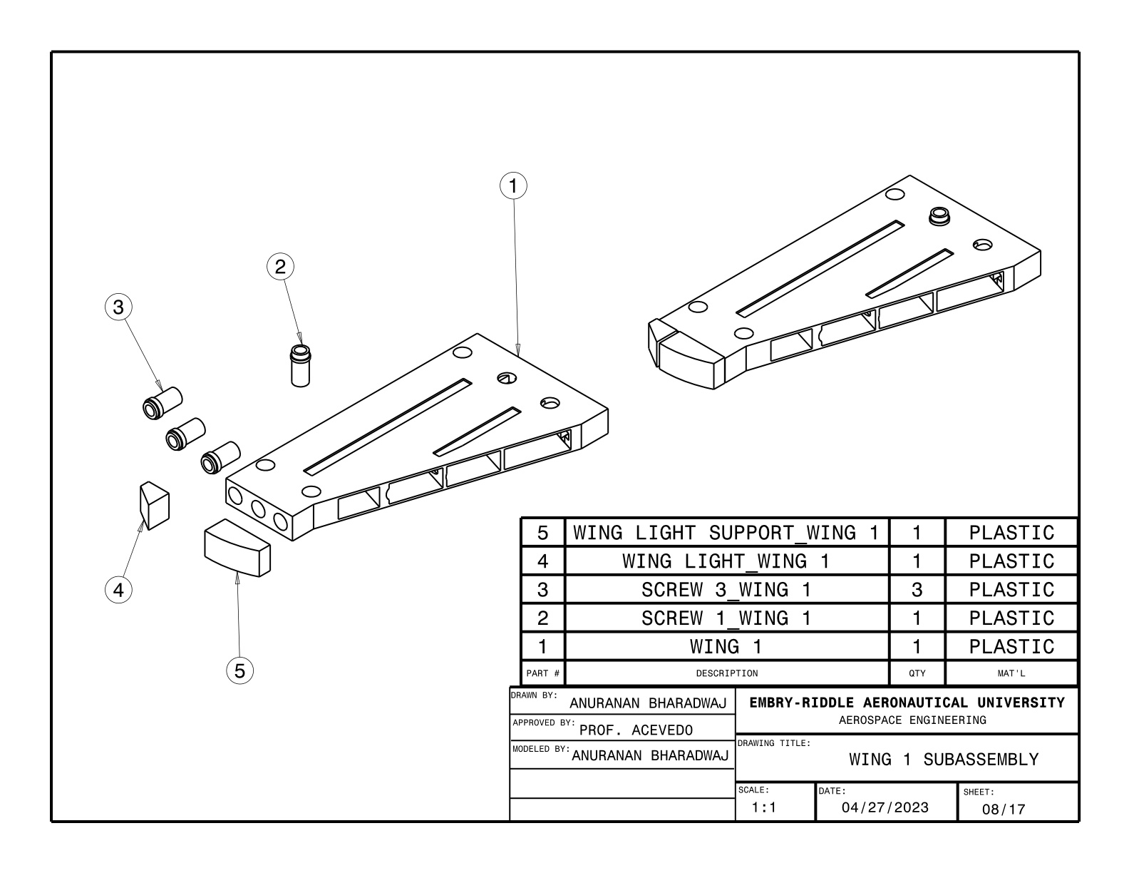
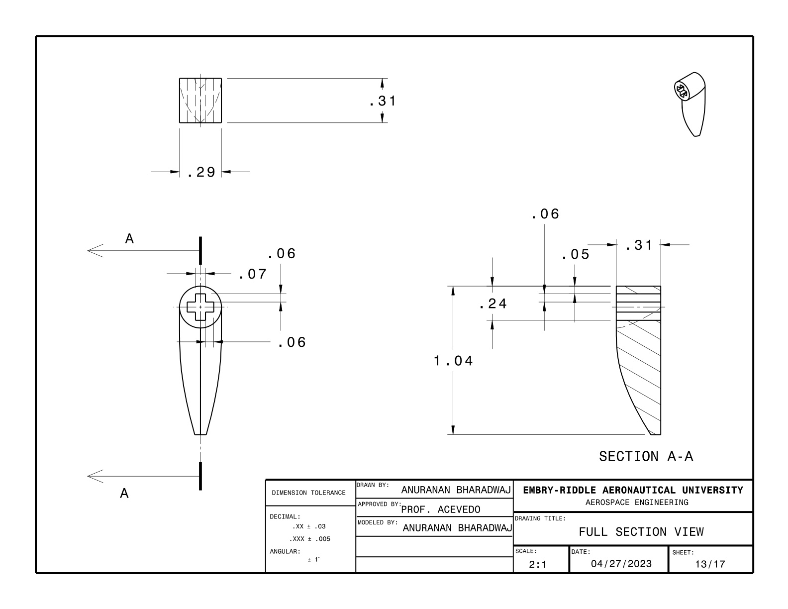
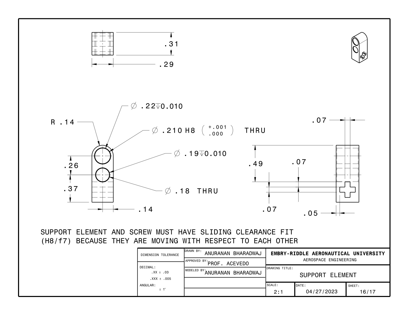
- Document the design in a formal SolidWorks drawing package following engineering drafting standards
- Compare the LEGO design to real aircraft configurations and identify analogous design features